View Plc Logic Ladder Diagram Pics. It is a graphical plc programming language which expresses logic operations with symbolic notation using ladder diagrams, much like the rails and rungs of a traditional relay logic. The two vertical lines are called rails and attach to opposite poles of a power supply, usually 120 volts ac.
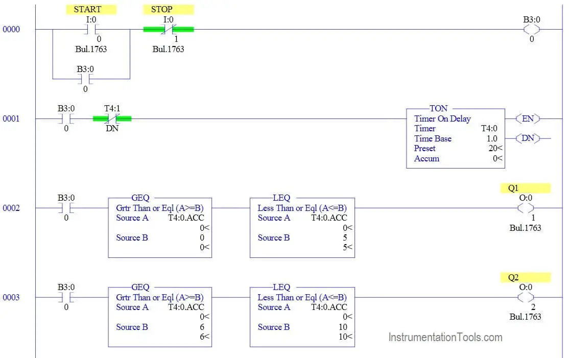
Ladder Logic Example with Timers - InstrumentationTools from cdn.instrumentationtools.com There are some methods to do plc programming. Ladder logic is a programming language that is used to program a plc (programmable logic controller). Different types of ladder logic diagram that perform different logic gate functions.
Where can i learn plc programming (ladder logic) online?
Hi friends here we are starting here a series of free training on plc la. A program in ladder diagram notation is a circuit diagram that emulates circuits of relay logic hardware. Again, this could be any output device that can be controlled by the plc: 1.3.11 how to design a rung.

0 Response to "Plc Logic Ladder Diagram"
Post a Comment