Get Plc Ladder Diagram Guide Pics. Ladder diagrams are to be thought of as virtual circuits, where virtual power flows through virtual contacts (when closed) to energize virtual relay coils to perform logical functions. The ladder diagram is the universal programming language of plc.
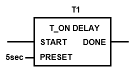
PLC Timer - Ladder Logic World from ladderlogicworld.com N append above to the leading two rungs of relay ladder logic diagram n switch a and switch b are connected to discrete input channels of the plc n light is connected to discrete output. Ladder diagrams are to be thought of as virtual circuits, where virtual power flows through virtual contacts (when closed) to energize virtual relay coils to perform logical functions. After a ladder diagram editor has been used to.
Ladder diagrams comprise a graphic language widely applied in automatic control, and.
In ladder logic the input can be arranged in either series or parallel. Background and functions of 1 basic principles of p. The only difference is that because the plc was very flexible in terms of the input and output devices, the symbols for the electrical devices are now exempted from the actual program. Create a ladder pattern, plc program designed is completed.

0 Response to "Plc Ladder Diagram Guide"
Post a Comment